Why does the Line Voltage lead the Phase Voltage in a 3-Phase Wye?
If you follow the orange arrows on the diagram below starting at Point A it moves through the phase windings to Point N and then from Point N through the load to back to Point A.
This means that the Line A voltage is the phasor sum of VAN and VNA.
VA = VAN + VNA.
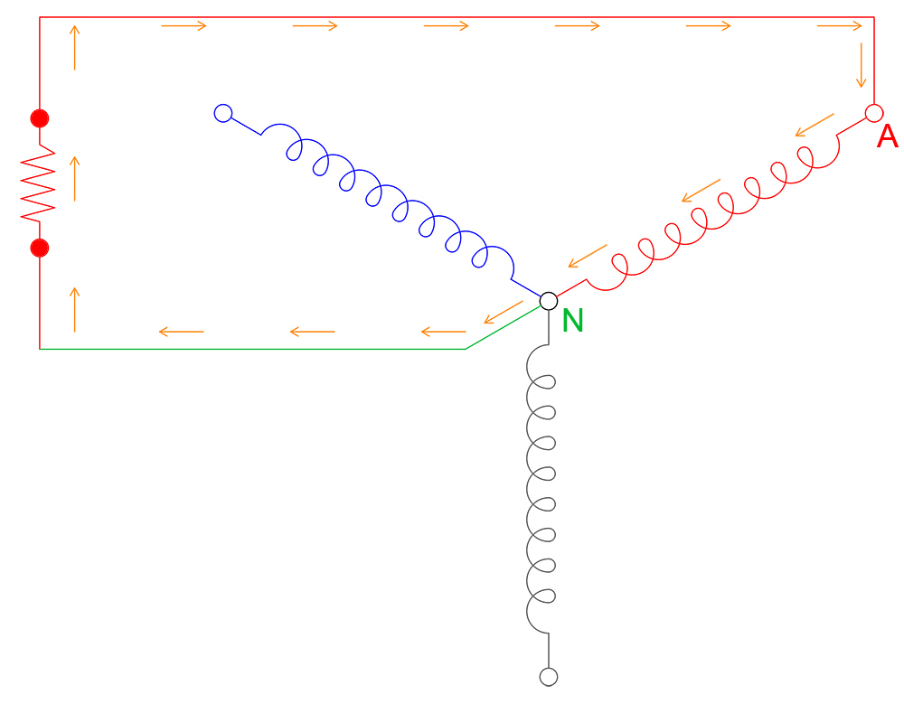
The Line Voltage VAB (Line A) is the phasor sum of of VAN and VNA. VNA is the same magnitude as VBN but with the opposite polarity.
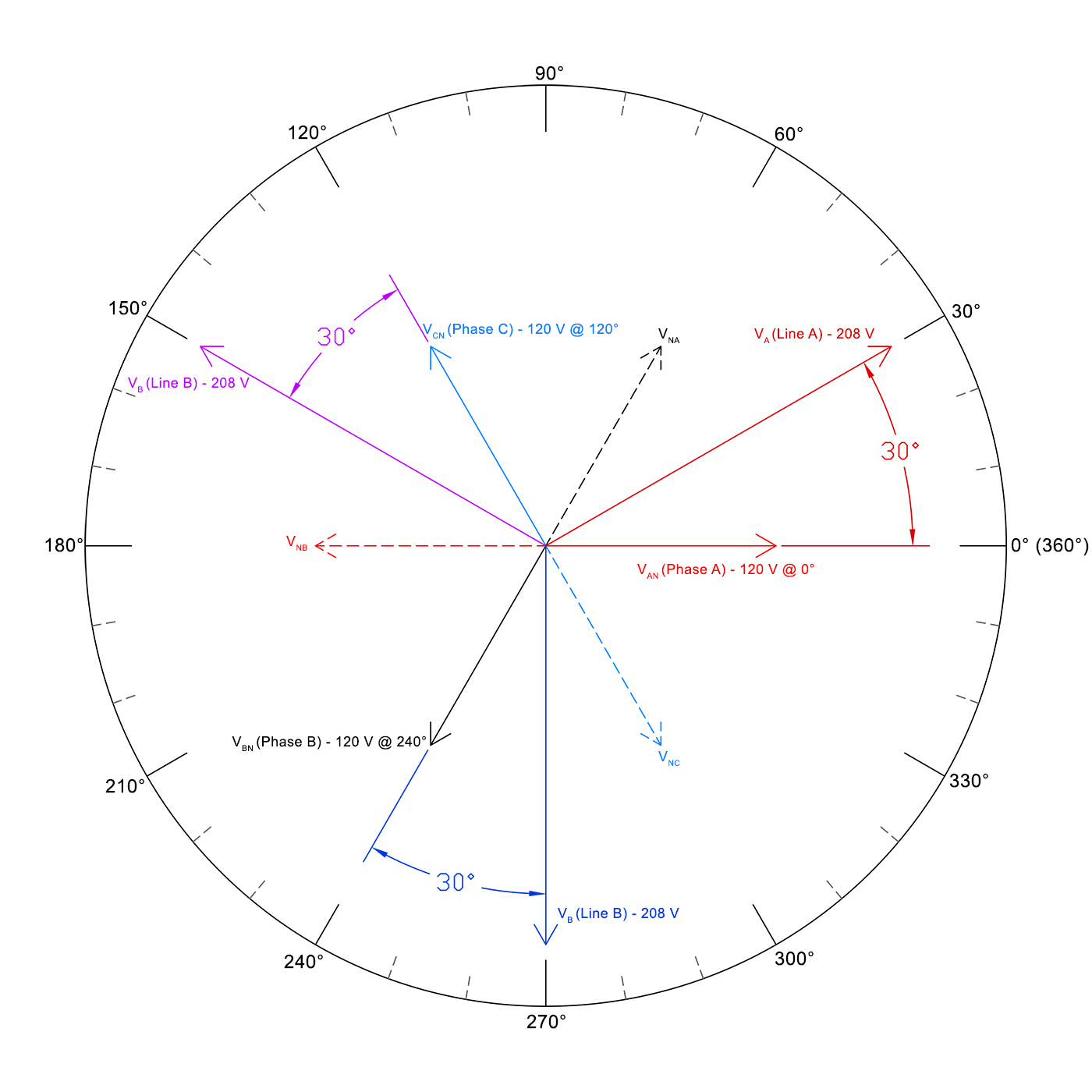
Phase A = 120 V @ 0° | Phase NA = 120 V @ 180°
Phase B = 120 V @ 240° | Phase NA = 120 V @ 60°
Phase C = 120 V @ 120° | Phase NC = 120 V @ 300°
Knowing this, let's find the Line Current for Line A.
VA = VAN + NNA
VA = 120 V @ 0° + 120 V @ 60°
| Horizontal | Vertical | |
|---|---|---|
| VAN = 120 @ 0° | 120.0000000 | 0.0000000 |
| VNA = 120 @ 60° | 60.0000000 | 103.9230485 |
| Totals | 180.0000000 | 103.9230485 |
Using Pythagorean Theorem, we know that C2 = A2 + B2
Line A2 = 1802 + 103.92304852
Line A2 = 43,200.00001
Line A = 207.8460969
Now we just need to determine the angle that Line A is at. To do this, we take our Total Horizontal Value (180) and divide that by our Line A value (207.8460969).
PfA = Horizontal Total / Line A
PfA = 180 / 207.8460969
PfA = 0.865900421
Line A ∠ = cos-1(0.865900421)
Line A ∠ = 30.01431877
VA = 207.8460969 @ 30.01431877° OR (208 V @ 30°)
Below is a phasor diagram that shows the three phases, their corresponding inverse phases and the Line Voltages.